Locator Lite XT
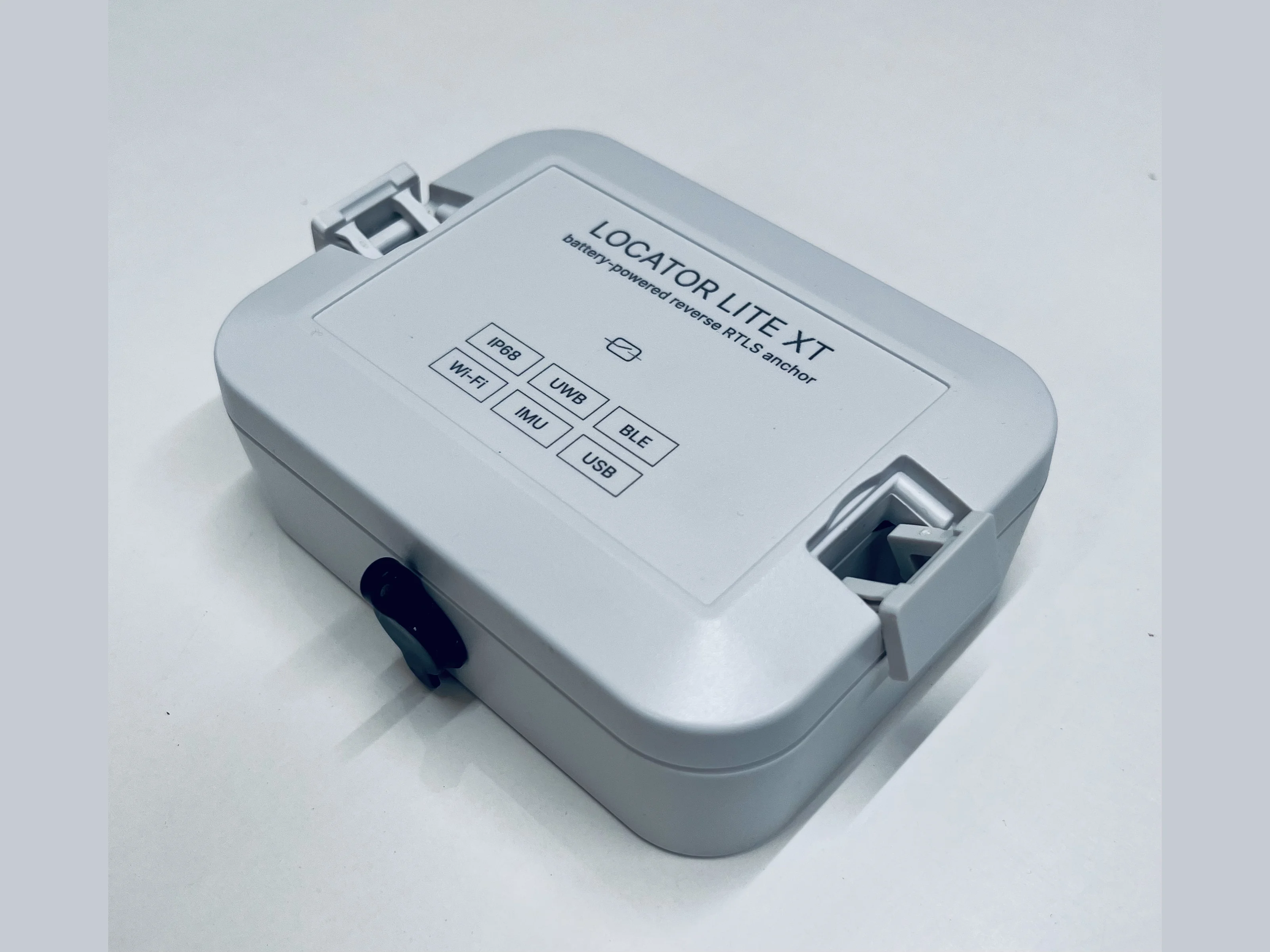
Battery-powered device for L-MESH nodes with the reverse RTLS tracking features for industrial equipment in places with no network coverage.
This is the main model to form L-MESH networks capable of running several years on the same accumulator charge. Locator Lite XT devices are also used as RTLS tags for industrial equipment, such as dewatering pumps, with Offline-online RMA and GATT Data Sync features to handle the situations when no mesh networks (or any other networks) are present at all.
Key specifications
| Enclosure | |
|---|---|
| Rating | IP67-IP68, ready for dust and water; tested at 1+ meter water depths; |
| Dimensions | 10 cm x 7.5 cm x 3.5 cm |
| Material | ASA, UV-resistant |
| Chipsets | |
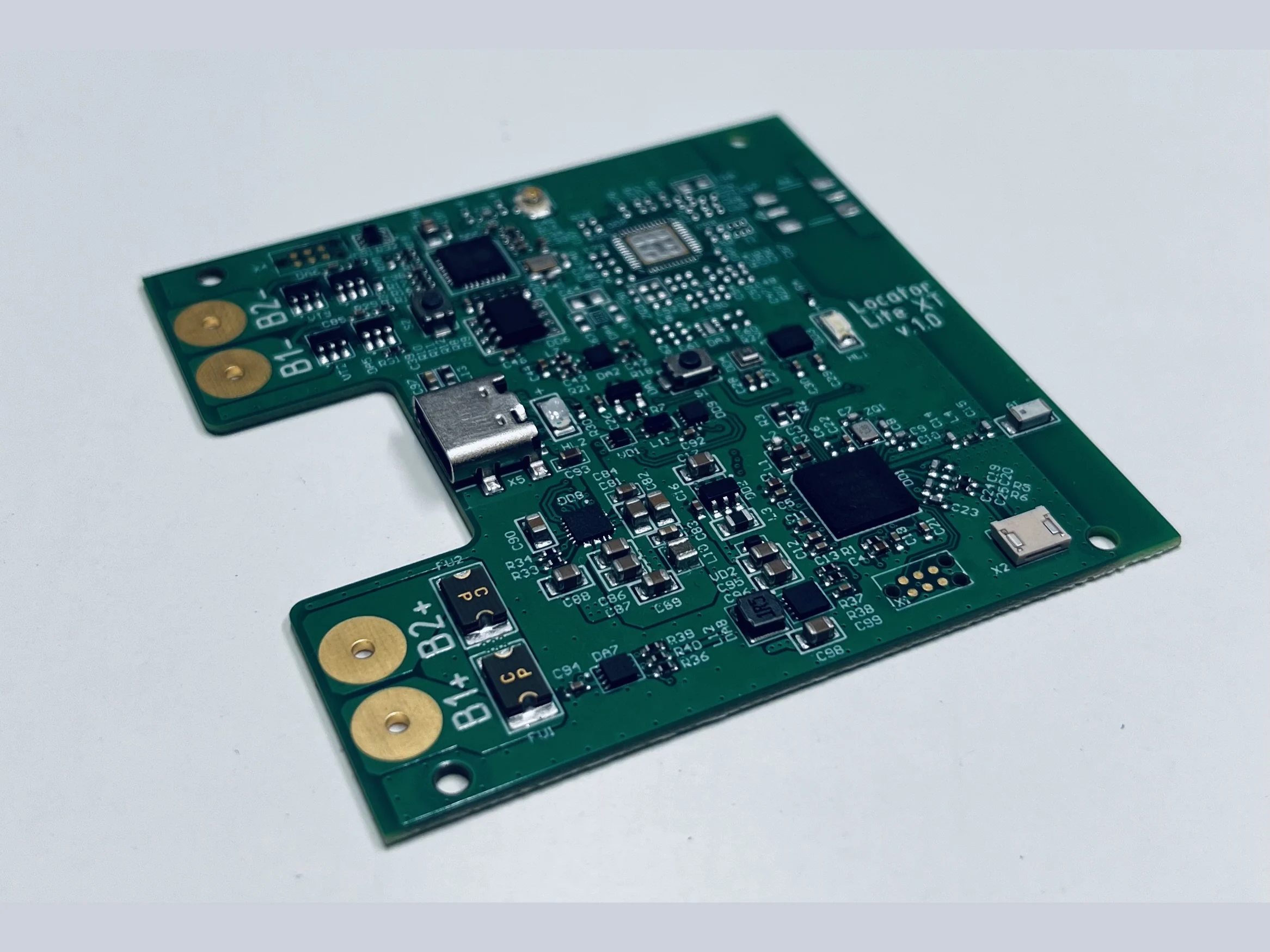
| MCU + BLE | Nordic nRF52840 (BLE 5, 802.15.4) |
| UWB | Qorvo/Decawave DW1000 |
| Wi-Fi | Espressif ESP8266EX |
| Sensors | |
| IMU | Bosch BMI270 (6-axis accel + gyro) |
| Barometer | Bosch BMP390 |
| Hall sensor | Allegro APS11753 |
| Battery | |
| 2 × Li-ion 21700 (50E) in parallel | |
| 9600 mAh / 3.6 V nominal / ~34.5 Wh | |
| Per-cell protection (overcharge / overdischarge / overcurrent) | |
| Charging | |
| Charger IC | ADI MAX77751 |
| Fuel gauge | ADI MAX17048 |
| Connector | USB Type-C, CC current detection + BC1.2 |
| Fast charge | 3.15 A |
| Connectors | |
| Debug | Tag-Connect TC2030-IDC for the nRF52840 and the ESP8266 |
Interfaces
| Interface | Notes |
|---|---|
| L-MESH | mesh node role — relay for RTLS, telemetry and alarms |
| L-DCB | 2.4 GHz differential positioning over the mesh radio |
| Offline-online RMA | topological position; the device's positioning method |
| BLE GATT | fleet characteristic map, plus 0x5136–0x513B |
| GATT Data Sync | the device's only JSON channel |
| Battery reporting | fuel gauge; charge and external-power flags |
| Sensor TLV | record definitions present on the product |
| Hall Sensor | magnet power on / off gesture |
| MQTT | payload keys and topic suffixes defined |
| OTA Upgrade | single signed ZIP over BLE |
UWB and WiFi parameter groups accept writes and persist them, and the device reports "applied": false for both. No CAN or RS-485 controller is fitted.
Reverse RTLS
Conventional RTLS puts anchors in the infrastructure and tags on assets; this product inverts that. Inexpensive BLE beacons are fixed along the route, and the device on the asset scans them and stores its position against matchpoints — virtual reference points placed on the map in the web portal, corresponding to known fixed points on the site such as survey pegs. See Offline-online RMA.
Because the device is the subject of its own tracking, it publishes under its own LocatorID in the {prefix}/Locators/ tree — the beacon identities in the payload are fixed infrastructure, not tracked tags. See Offline-online RMA for the algorithm and record format.
Buffer and sync
Matchpoints accumulate on the device and are handed over when a reader comes into range, through the GATT Data Sync drain. Records are erased only after the response has been read to its end; an interrupted handover leaves them in place.
On this product match_points is the default store when a command omits type — sensor and gnss are recognised and explicitly refused rather than answered from the wrong store.
GATT migration note
0x5101and0x5102changed meaning. They previously carried this product's JSON request / response pair; they are now Serial Number and BLE MAC, matching the rest of the line. The JSON channel is at0x5130/0x5131only.
An application written against the old pair must be repointed. Payloads and commands are unchanged — only the handles moved — and 0x5130 also accepts the original dialect, so handles and payloads can be migrated in separate steps. A client caching handles must rediscover the service.
Reverse-RTLS settings
Settings specific to this mode occupy 0x5136–0x513B: scan period, WiFi sync, sync-on-beacon, hardware, beacon major and beacon minor. These UUIDs are reserved fleet-wide.
Power and charging
Cells
| Cells | 2 × 21700 Li-ion, in parallel |
| Capacity | ≈ 9600 mAh |
| Nominal | 3.6 V |
| Full | 4.20 V |
| Empty | 3.00 V |
The cells are in parallel, not series. Capacity doubles; voltage does not. Every millivolt figure above and in every battery report is a single-cell voltage — a reader expecting a two-cell pack would judge a healthy 4.2 V pack to be half flat.
The large capacity is what makes the device's job possible: it is fitted to equipment that sits unattended for weeks with no power and no coverage, so the battery has to outlast the interval between visits rather than a shift.
Fuel gauge
A MAX17048 ModelGauge sits on the pack at I²C address 0x36 (7-bit) and reports cell voltage and state of charge directly — no divider, no discharge curve in the firmware path.
| Register | Field | Scaling |
|---|---|---|
0x02 | VCELL | 78.125 µV/LSB — exactly 5/64 mV, so the conversion is integer-exact |
0x04 | SOC | 1/256 % per LSB |
0x08 | VERSION | reads 0x001x; checked against mask 0xFFF0 |
0x0C | CONFIG | [15:8] RCOMP, [7] SLEEP, [6] ALSC, [5] ALRT, [4:0] ATHD |
0x16 | CRATE | 0.208 %/hour per LSB — charge or discharge rate |
ATHD is encoded as 32 − threshold%, so the 15% low-battery alert is written as 17. RCOMP is left at its default.
VERSION is read before any measurement is trusted. Anything outside 0x001x is a different part, a dead bus, or a floating SDA line reading 0xFFFF — all of which produce no reading rather than a number.
Poll rates differ by two orders of magnitude and deliberately so: charger sense every 250 ms, so a plugged cable registers promptly, and the gauge every 60 s, because state of charge moves over hours and each read costs an I²C transaction.
Charger status
Two charger lines reach the MCU, so the charging and external-power flags carry measured values rather than assumptions:
| Line | Asserted means |
|---|---|
| Charge status | the charger is actively charging |
| Input valid | a usable external supply is present |
Both are open-drain and pull low when asserted, with the MCU supplying the pull-up. The gauge also has an alert line back to the MCU, so a low-battery threshold at 15% is signalled rather than waiting to be noticed on the next poll. State of charge is otherwise polled slowly — it moves over hours, and each read costs energy.
Battery reporting
Battery state travels as Sensor TLV record 0x09 and appears in the Battery object of an MQTT /Sensors message — millivolts, percentage and flags together.
A percentage of 255 means the reading was implausible — a scaling or sense fault — not a flat cell. Because the pack is a known chemistry with a known window, a voltage outside that window is evidence the measurement is wrong rather than that the battery is empty. See Sensor TLV for how to tell that apart from a device with no cell fitted.
Runtime
Working life between charges depends on the scan interval, sync frequency and how often a reader is in range, so it is set by configuration rather than by the hardware alone. Determine it by measurement against the intended duty cycle for a deployment.
Magnet power control
The device has no power button. It is switched on and off with a magnet held against the marked spot for two seconds — see Hall Sensor for the full behaviour.
| From | Action | Result |
|---|---|---|
| Off | hold a magnet 2 s | boots and starts working |
| Off | brief contact | wakes, fails the hold test, returns to off |
| Running | hold a magnet 2 s | three blinks, a one-second pulse, then off |
The hold requirement is what separates a deliberate action from a device brushing past a magnet in transit. A 15-second cooldown applies after each switch, so a magnet left resting on the device cannot toggle it repeatedly, and the LED sequence is the only confirmation on an enclosure with no screen.
Because the enclosure needs no button or switch through its wall, it can be fully sealed. That is the reason for a magnet rather than a control the wearer can press.